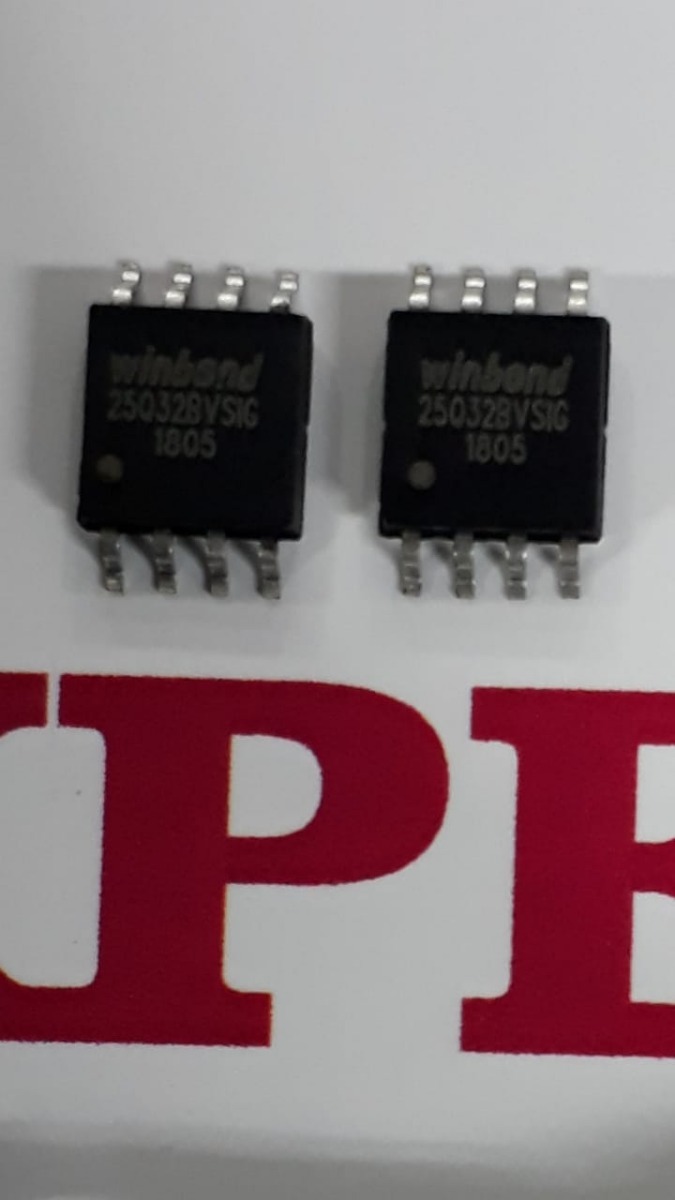
Winbond 25q32 Programmator
USB Programmer CH341A Series 24 EEPROM BIOS LCD Writer 25 SPI. W25Q32BVSSIG IC SPI FLASH 32MBIT 8SOIC 25Q32 W25Q32 SOP8 New Original(. Sep 20, 2015 - A Flash SPI programmer is an essential engineering tool that has been done over and over. Adding a new part: the Winbond 25Q32 2.
If you are simply looking for a way to program the Winbond SPI flash with 'pre-loaded' data that your microcontroller would read for use when it is running then what you will want to look into is a programmer that can do in-circuit programming of the SPI Flash chip. This also known as in-system-programming (ISP). One choice is the. This USB connected device can program in circuit if you design your board correctly. They even sell an adapter clip that can attach into the SOW-16 package without having to design in a separate programming header on your board. DediProg has application information bulletins available to help with correct design for in circuit use.
The main strategy for the design is to find a simple way to isolate the SPI interface drivers in your MCU system so that they do not interfere with the drivers in the SPI programming pod. The simplest way to do this is to put series resistors in the MCU driven lines between the MCU and the SPI Flash. The programmer would connect on the SPI flash side of the series resistors. Alternate methods could include adding a MUX or analog switches in the driven interface lines. An even more clever scheme is to add a 'programming enable' input to the MCU that makes the software disconnect all the SPI I/Os from the SPI Flash chip (i.e.
Make all those GPIOs as inputs). A second choice to also consider is. The Presto is able to do various types of SPI and I 2C devices including SPI Flash devices. I have one of these devices specifically for programming Atmel MCUs and various types of SPI Flash devices. It is a more cost effective solution than the above unit but not quite as flexible. Their more expensive device called the Forte is able to do more things because it has more target interface pins.
Sometimes it can be beneficial to be able to connect a programmmer to a target board without having to add a programming header. One nice solution for this is to place a small set of pads in a special footprint defined. They manufacture and sell a series of quick connect programming cables that have pogo pins that engage the special footprint on the board. There are 6-pin, 10-pin and 14-pin versions of the cable available to suit a range of applications. Cost of the cables are very reasonable. I have never heard of any other tools talking SPI directly to such a chip, and I think it is impossible since 'all' chips require different calls for different operations. The chip needs SPI calls for write, read, change sector, data size etc.
Ease acoustic software crack downloads for windows 10. EASE - Enhanced Acoustic Simulator for Engineers The EASE software suite provides system designers and consultants with an invaluable set of tools for all aspects of professional practice, from detailed, realistic modeling and simulation of venue acoustics and sound system performance to informative and engaging client presentations, as well as.
Under 7.2 Instructions chapter in the datasheet you can see all the SPI commands you can send to it. Hence, since all external flash memories does not have the same instruction set, you need to write a customized application for this one. EDIT: Being a follow up, I would really recommend one of Atmels own SPI flash memories, since most of them already has written open available code for them.  Looking at from will provide you with code for some of Atmels AT45xxxx serial flash chips. I purchased a ' programmer from Embedded Computers for about $30 US. It was surprisingly easy to connect to the PC via USB and write files to the Winbond flash memory.
The methods and programmers in other answers are probably just as good, some more expensive or DIY, but this is a cheap and simple way that fits what I was seeking. Here's a picture of the setup: The FlashCAT programmer is at left, connected to USB. It's running the SPI programming firmware (as opposed to JTAG) and supplying power to the flash memory. The supplied power is selectable (3.3V or 5V) with a jumper. I have a SOIC to DIP socket on the breadboard to make it easy to program multiple chips. (You can see another flash memory IC sitting on the breadboard as well.) I haven't yet converted my audio file to the proper binary format, but I wrote a 211KB WAV file to memory just to test, pictured above.